Lecture: 3D transformation and mouse/keyboard events
Coordinate spaces
Up until now, we've been drawing into a window in a coordinate space of [-1, 1] in X and Y. This is known as normalised device space, because the coordinate space is the same regardless of the size of the video device (the window).

A high-level representation of the graphics pipeline used in realtime rendering. Source: nVidia Cg Users Manual via http://blogs.vislab.usyd.edu.au/index.php/2007/03/
Recall that last week we mentioned the programmable vertex processor, and how it can transform vertices from the application's coordinate space into normalised space. While it can be programmed arbitrarily, it also contains a built-in fixed function pipeline that is useful enough for most purposes. This week we'll make use of this built-in functionality to specify our own coordinate space.
The fixed-function vertex pipeline transforms vertex coordinates in several stages.

First, the spaces that you are already familiar with:
- Object space is the coordinate space of the vertices you give with glVertex2f, etc. You can make this coordinate space represent anything at all (so long as it's linear). For example, the object space could be specified in meters, or kilometers, or microns -- typically an application will use many different object coordinate spaces within a single scene.
- Normalised device space has already been introduced. It is the [-1, 1] domain in X and Y.
- Window space is the pixel coordinates of the actual window on the screen.
To get from object space to normalised device space, the vertices pass through two other spaces: eye space and clip space.
- Eye space is the same as object space, shown from the view of the "camera" (there isn't actually any "camera" involved, but you can think of this space as defining where the camera is, implicitly).
- Clip space is a cube in 3D space ranging over [-Wc, Wc] in X, Y and Z. This is the space against which polgyons are clipped if they are outside the view frustum. You don't usually need to worry about clip space, it takes care of itself.
Linear transforms
Between each of these coordinate spaces is an affine (linear) transform that converts the vertices in the space on the left to the one on the right. We'll go into the mathematics of how this works later in the semester. For now, let's just consider an example.
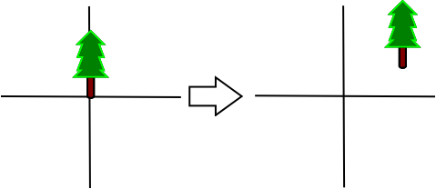
Let's say we need a transform that converts the vertices on the left to those on the right:

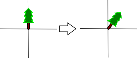
Clearly the vertices just need to be moved up and to the right. Such a transform is called a translation. Another example of an affine transform is rotation:

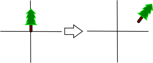
In this case, the vertices need to be rotated around the origin 45 degrees clockwise. Transforms can also be composed, as in this image:

The image shows the result of composing the rotation and translation above. You can think of it as translating the vertices first, then rotating them.
The order of composition matters! Consider the difference between the previous example and rotating the vertices first, and then translating them.
Transformations in OpenGL
So we now know that there is an OpenGL transformation from object (model) space to view (eye) space, but how do we change it from the default (which is the identity transform -- it does nothing)?
First, we call:
glMatrixMode(GL_MODELVIEW_MATRIX);
to specify that we want to modify the Model/View transform (refer back to the transform diagram).
glTranslate(x, y, z) composes a translation onto the end of the current transform, and glRotatef(angle, x, y, z) composes a rotation. To reset the transform back to the identity, use glLoadIdentity(). So, to create the transformation shown above, we'd write something like:
glMatrixMode(GL_MODELVIEW);
glLoadIdentity();
glTranslatef(3, 2, 0);
glRotatef(-45, 0, 0, 1);
Having set up the Model/View transformation, we can now draw a tree using that transformation:
glBegin(GL_TRIANGLES);
...
glEnd();
Remember to call glLoadIdentity() to draw something from the original untransformed coordinate space again.
Projection transformations
The projection transform moves vertices from eye space to clip space, which is just around the corner from normalised device space. The projection transform is usually used to map 3D coordinates into a 2D plane suitable for viewing on a computer screen.
There are two commonly used projection transforms:

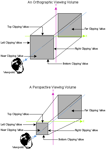
Projection transforms. Source: http://www.microsoft.com/msj/archive/S2085.aspx
- Orthographic projection is like an architect's side-on or top-down view of a model. Lines that are parallel in 3D remain parallel in the 2D projection. Orthographic projections are often used in OpenGL to render heads-up-displays or other user-interface elements.
- Perspective projection reproduces the effect of a pinhole camera, and is more commonly used in games and graphics applications, as it gives a better sense of depth. Parallel lines converge towards a vanishing point on the horizon.
To set the projection transform in OpenGL, first make it the active transform:
glMatrixMode(GL_PROJECTION);
Reset it to the identity transform (erases any previously set projection):
glLoadIdentity();
And then compose either an orthographic or perspective projection. The orthographic projection is:
glOrtho(left, right, bottom, top, near, far);
where left, right, bottom and top give the bounds of the new coordinate space; and near and far specify clipping values for the Z axis. For example, if we prefer to draw into a coordinate space ranging in [0, 100] along X and Y instead of the default [-1, 1]:
glOrtho(0, 100, 0, 100, -1, 1);
The perspective projection requires you to first #include <GL/glu.h> if you have not done so already; then:
gluPerspective(fov, aspect_ratio, near, far);
where fov is the vertical field of view, in degrees; aspect_ratio is the ratio of the screen width to height; and near and ``far give the Z coordinates of the near and far clipping planes (see the diagram above; both must be greater than zero). A typical perspective projection is:
gluPerspective(75, width / (float) height, 0.1, 1000);
When finished setting the projection change the matrix mode back to model view
glMatrixMode(GL_MODELVIEW);
Viewport transformation
In the diagram at the beginning of the lecture, the viewport transform is shown to map normalised device coordinates (in the range [-1, 1]) to window space coordinates (actual pixel values).
By default GLUT sets up this transform for us, mapping the entire window. When we create a window resize function, however (for example, to respond to changes in width and height to recreate the projection transform), we need to do it ourselves.
Use glutReshapeFunc() to set up a callback for when the window is resized by the user:
void reshape(int width, int height)
{
}

int main(...)
{
    ...

    glutReshapeFunc(reshape);
}
Within the reshape function we need to set the viewport transform. Unlike the model/view and projection transforms, this one is set with a single function call, and does not compose transforms:
glViewport(x, y, width, height);
where x and y give the lower-left coordinates of the viewport within the window, and width and height the dimensions of the viewport. Usually we want the viewport to fill the whole window, so:
void reshape(int width, int height)
{
    glViewport(0, 0, width, height);
}
You can now set the projection transform inside the reshape function to have the projection keep up-to-date with the window size.
Mouse and keyboard events
We've already seen a few GLUT function callbacks: display, idle, reshape. Let's introduce a few more:
- glutMouseFunc() sets a callback for mouse(int button, int state, int x, int y), which is called whenever a mouse button is pressed or released.
- glutMotionFunc() sets a callback for motion(int x, int y), which is called when the mouse is dragged in the window.
- glutKeyboardFunc() sets a callback for keyboard(unsigned char key, int x, int y), which is called when a key on the keyboard is pressed.
You should work through the tutorial to get a better understanding of how to use the mouse functions. Remember to consult the GLUT manual for details on these and other functions.