Lecture: Introduction to 3D Graphics
Course overview
This course is an introduction to programming 3D computer graphics. We will cover some basic 3D modelling, texturing and animation, and you will write C or C++ programs that implement these processes. The following background skills and knowledge are assumed:
- The ability to write programs in C or C++ from scratch.
- Mathematics at the VCE level
- The ability to work comfortably in a Unix-like environment.
All work in this course is to be done on Linux workstations. These are similar to the Unix environments used in other Computer Science subjects, so you should not have much trouble adapting.
The topics we will cover (which may change) are as per the course guide and the schedule on the main course webpage
Most of the tutorial/lab sessions in this course are designed to help you implement your assignments. It is highly recommended you attend these classes as you will find it quite difficult to complete the assignment without some help. You will also need to spend some time in the lab outside of scheduled class times working on the assignments.
Due to the short deadlines on assignments you will need to get started early. In the event that you do not complete an assignment, or do so poorly, we will provide a reference solution which you can use to base your next assignment on. So, for example, if you don't finish assignment 1 on time, you can start on assignment 2 from the provided solution so as not to waste any more time. Alternatively, you may prefer to work from your own code base; there is no penalty either way.
3D graphics
Computer-generated images of 3D scenes are produced by a rendering technique. Generally in computer graphics, as elsewhere, you get what you pay for: higher quality images require more computation time. In real-time applications (say 30 frames per second or higher) such as games where interactivity is important, quality is traded for speed.
Four key rendering techniques are rasterisation, ray tracing, radiosity and photon mapping. In this course we will concentrate on rasterization, which is used in graphics cards.
A key aspect of the quality of images produced by a rendering technique is whether it uses local or global illumination. Global illumination techniques attempt to capture the effects objects have on other objects - such as shadows and colour bleeding. Local illumination approaches ignore them. and are faster. Rasterization uses local illumination whereas ray tracing for example uses (a form of) global illumination.
In true global illumination, rendering software would simulate the emission of photons from light sources and their subsequent trajectory through a scene. It is relatively simple to derive the global illumination algorithms from the real-world physics models on which they are based. Almost any illumination effect can be simulated with global illumination, including diffuse scattering, reflectance and transmitance, effects of gravity and diffraction, interference, and so on.
Due to the enormous number of photons involved, stochastic techniques are usually used to make the computation tractable. For example, a single photon in the simulation may represent the probable locations and velocities of several thousand photons. Even with these assumptions, global illumination is prohibitively expensive in terms of computation time. Consider the number of photons whose path is computed only to have them bounce out of the "scene" instead of into the virtual camera's lens. The quality of the image produced is related to the number of photons allowed in the scene: too few results in grainy-looking images.
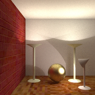
Global illuminated scene. Source: http://www.cgl.uwaterloo.ca/Projects/rendering/Talks/swc/pres26.html
In ray tracing, the process of photons bouncing around a scene is run in "reverse". Visibility (or primary) rays are projected from the camera lens into the scene and the object they intersect determined. Then recursively reflected and refracted rays are traced, for some predetermined depth. Shadow rays are also traced to see if a point on a surface is lit directly by a light or whether an object casts a shadow. When ray tracing an image, you can usually trace one ray for every pixel in the image (or some slightly higher number if multisampling is used). Obviously this results in far fewer rays being traced, and hence fewer calculations performed.
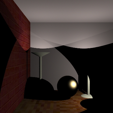
Ray-traced scene. Source: http://www.cgl.uwaterloo.ca/Projects/rendering/Talks/swc/pres26.html)
Ray tracing cannot simulate all the effects of global illumination. Whilst it does capture specular inter object reflections well, diffuse effects such as caustics and colour bleeding cannot be (easily) reproduced. Ray-tracing is often combined with other global illumination techniques such as radiosity or photon mapping. Ray tracing is well-suited to large, complex scenes but can take a long time to render just a single image. Studios such as Pixar and Weta run thousands of networked computers to render movie scenes.
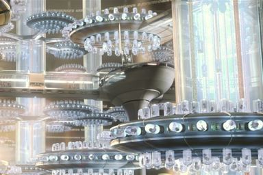
Scene from Star Wars rendered in mental ray, a modern ray tracing tool. Source: http://www.mentalimages.com/4_1_motion_pictures/index.html
For interactive applications, the only technique that is feasible with current hardware is rasterization. The geometry is rasterized into pixels in image space, one triangle or polygon at a time. No inter-object effects are considered, and hence rasterization is a local illumination approach. Adding complexity to the scene (in the form of more geometry i.e. more polygons) increases the time to render in a linear relationship.
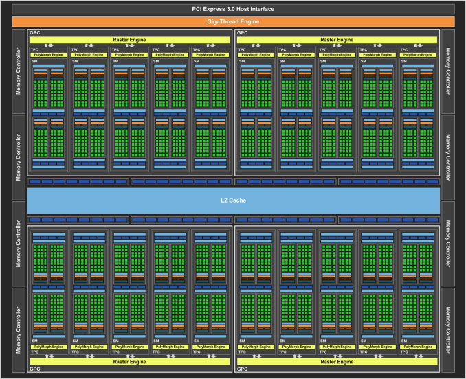
Modern graphics cards are specially designed to accelerate rasterization by handling multiple triangles and pixels at once (parallelising the operation).
The GeForce GTX 1060s GPUs in the Sutherland laboratory have 1280 processors, or cores, 4.4 billion transistors. The GTX 560s from 5 years ago had 480 cores and 1950 million transistors.
An nVidia GeForce GTX 1080 "Pascal" GPU has 2560 shader (or CUDA) processors/cores, 7.2 billion transistors, 8 GB of GDDR5X memory, memory bandwidth of 320 GB/s, and can write 102.8 billion pixels per second (source: Nvidia webite).
A previous generation nVidia GeForce GTX 980 "Maxwell" GPU has 2048 shader (or CUDA) processors/cores, 5 billion transistors, 4GB of GDDR5 memory, memory bandwidth of 224 GB/s, and can write 72.1 billion pixels per second
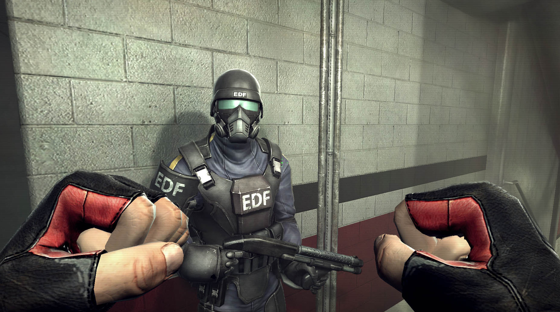
Example scene from GeForce GTX 560 website Source: http://www.geforce.com/News/articles/560-game-previews-page2
The details of how rasterization, and in particular scanine rendering works will be covered next week.
OpenGL
OpenGL is a standard agreed upon by video card manufacturers and software developers for rendering 3D graphics efficiently. The complete specification is available for free at http://www.opengl.org.
The current version of OpenGL is 4.5, released late last year and for which drivers are just becoming available. There are also numerous extensions to the specification that manufacturers provide so that the latest features of their video cards can be used before the specification is ammended.
In this course we'll mostly be using features from OpenGL 1.1, which has been supported by every video card and operating system since 1995 or earlier, and OpenGL 2. The 1.1 edition of the OpenGL Programming Guide (often referred to as the "Red Book") is available online for free. One of the big changes changes in OpenGL 2 was the introduction of shaders. OpenGL continues to evolve, with versions 3 and 4 introducing further features. This year a new lower level graphics API called Vulkan is being introduced by Khronos, a non-profit industry standards group.
Programming with OpenGL
Because OpenGL is a public standard, there are many implementations and interfaces to it. OpenGL-capable programs can be written in C, C++, Java, Perl, PHP, Python, ... there are bindings for most languages. Most OpenGL programs are written in C or C++.
Because OpenGL defines only the raw graphics interface, it doesn't provide any means to open a window on the desktop, respond to the mouse or keyboard, or any number of other common activities required by even a simple graphics program. Simple libraries are available which do provide this capability, and most of them are free. Some of the common ones are:
- GLUT
- The "traditional" C library used to write simple OpenGL applications: it's available for Windows, Linux, OS X and other platforms, and is the library we'll be using in this course.
- SDL
- Another C library that provides more features than GLUT, such as joystick support, but is harder to work with. We'll use SDL in next semester's course Realtime Rendering.
- GTK, KDE, GDI, MFC, WinForms, Cocoa, Carbon, ...
- These are the "native" windowing libraries for Linux, Windows and OS X. They all provide OpenGL contexts.
Java, Python, Perl, etc also provide their own set of libraries or bindings to the C ones above.
A "GLUT/OpenGL" program is just like any other C program, it just links to some extra libraries. Here is a very simple program, that just opens a blank window:
#include <stdlib.h>
#include <stdio.h>

#include <GL/gl.h>                                              /* 1. */
#include <GL/glu.h>
#include <GL/glut.h>

void display()                          /* 2. */
{
  glClear(GL_COLOR_BUFFER_BIT | GL_DEPTH_BUFFER_BIT);     /* 3. */

  /* Draw something here */

  glutSwapBuffers();                      /* 4. */

  /* Always check for errors! */                /* 5. */
  int err;
  while ((err = glGetError()) != GL_NO_ERROR)
    printf("display: %s\n", gluErrorString(err));
}

int main(int argc, char **argv)                 /* 6. */
{
  glutInit(&argc, argv);                    /* 7. */
  glutInitDisplayMode(GLUT_RGB | GLUT_DOUBLE | GLUT_DEPTH);
  glutCreateWindow("Tutorial 1");               /* 8. */
  glutDisplayFunc(display);                   /* 9. */
  glutMainLoop();                       /* 10. */
}
We include gl.h (the C OpenGL header file) and glut.h (the GLUT header file) first. These define the prototypes for the gl* and glut* functions used in this file. glu.h is not used in this program, but contains some common functions we'll use later in the semester.
We define a display() function that will take care of drawing inside the window.
Currently, the only drawing we do is to clear the contents of the window, so it's black. We'll talk about the meaning of the GL_* parameters next week.
This is a function that needs to be called at the end of the display function. We'll discuss it more next week, but for now just think of it as a function that says "I'm done drawing now, please update the window."
- Check for errors! Always. Fundamental to program development and debugging.
The main() function is where the program starts runnning, like in any other C program.
We must call glutInit() before using GLUT, passing in the command line arguments given to the program.
Together, glutInitDisplaymode() and glutCreateWindow() open a new window. We'll discuss the meaning of the GLUT_* arguments next week.
In a moment, GLUT is going to take over running the program. When it does, we need to make sure it calls back into our program to perform certain tasks, such as drawing inside the window.
With glutDisplayFunc(display) we tell GLUT that we want it to call our own display() function whenever the window needs to be drawn in. We never call this function ourselves -- GLUT calls it for us.
Finally, we call glutMainLoop() to begin the program. This function never actually returns! (When the user closes the window, GLUT simply exits the process).
Drawing primitives
OpenGL is a very low-level drawing interface; you cannot load an entire 3D model and display it with one function call. Instead, individual triangles, points and lines must be drawn separately by the application.
These drawing elements are called "primitives": although they are simple, they can be combined into more complex objects with some clever programming.
OpenGL supports these primitives:
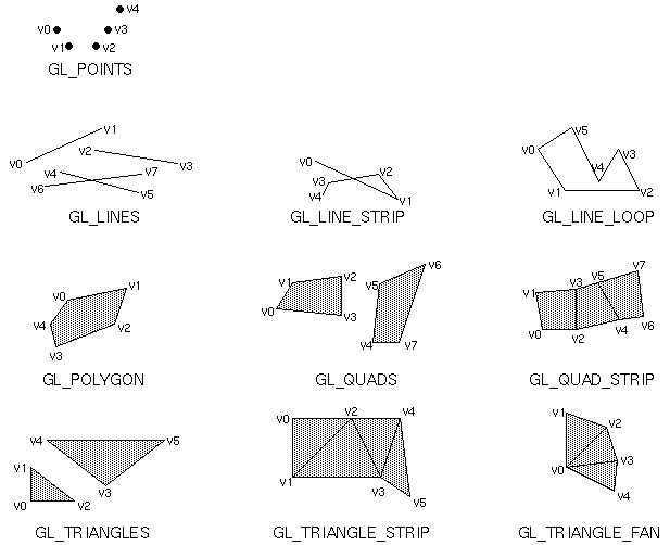
OpenGL drawing primitives. Source: OpenGL Programming Guide.
The following example draws three points:
glBegin(GL_POINTS);
glVertex2f(0, 0);
glVertex2f(0, 0.5);
glVertex2f(0.5, 0);
glEnd();
All primitive drawing starts and ends with glBegin() and glEnd(). The parameter to glBegin() tells OpenGL what sort of primitive to draw (the drawing mode). Any of the primitives shown in the figure above can be used.
Within the glBegin() and glEnd() pair, we tell OpenGL what vertices make up that primitive. In this case, each vertex is simply the position to draw each point -- one at (0, 0), one at (0.5, 0) and one at (0, 0.5).
If we change the mode to GL_TRIANGLES instead, a single triangle will be drawn that joins those three points together, as the vertices now specify the vertices of the triangle:
glBegin(GL_TRIANGLES);
glVertex2f(0, 0);
glVertex2f(0, 0.5);
glVertex2f(0.5, 0);
glEnd();
Notices that each vertex we specify corresponds to one of the v0, v1, ... vertices shown in the figure above. So, we could draw two triangles at once just by supplying the coordinates for v3, v4 and v5.
Vertex formats
Let's look at the function glVertex2f. OpenGL has many ways to specify a vertex position; this is just one of them. You can read it by breaking it up into its parts:
| glVertex | 2 | f |
| Type of attribute | Number of components | Data type of components |
For now we're only interested in the vertex position attribute glVertex, but later on you'll also see glColor, glNormal and glTexCoord; there are also several other more advanced attributes.
We are only giving 2 components (X and Y) at the moment because we're working in 2D -- on a flat screen. Later, when we start doing 3D stuff you'll be using glVertex3f to specify 3 coordinates (X, Y and Z).
The data type f refers to the C type float. This lets us give OpenGL values like "0.5". You can also use i for integer data, b for byte data, and so on. Usually f will do just fine.
Coordinate space
In your tutorial, plot the points given in the examples above and determine where they fall. While OpenGL can use any coordinate system, the default one (the one we're using at the moment) has X running from left-to-right along the screen from -1 to 1; and Y running from bottom-to-top up the screen from -1 to 1.
In later weeks we'll see how to modify this to suit our needs and create 3D projections.
 (source: